MARK II Cryomodule
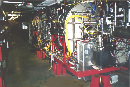
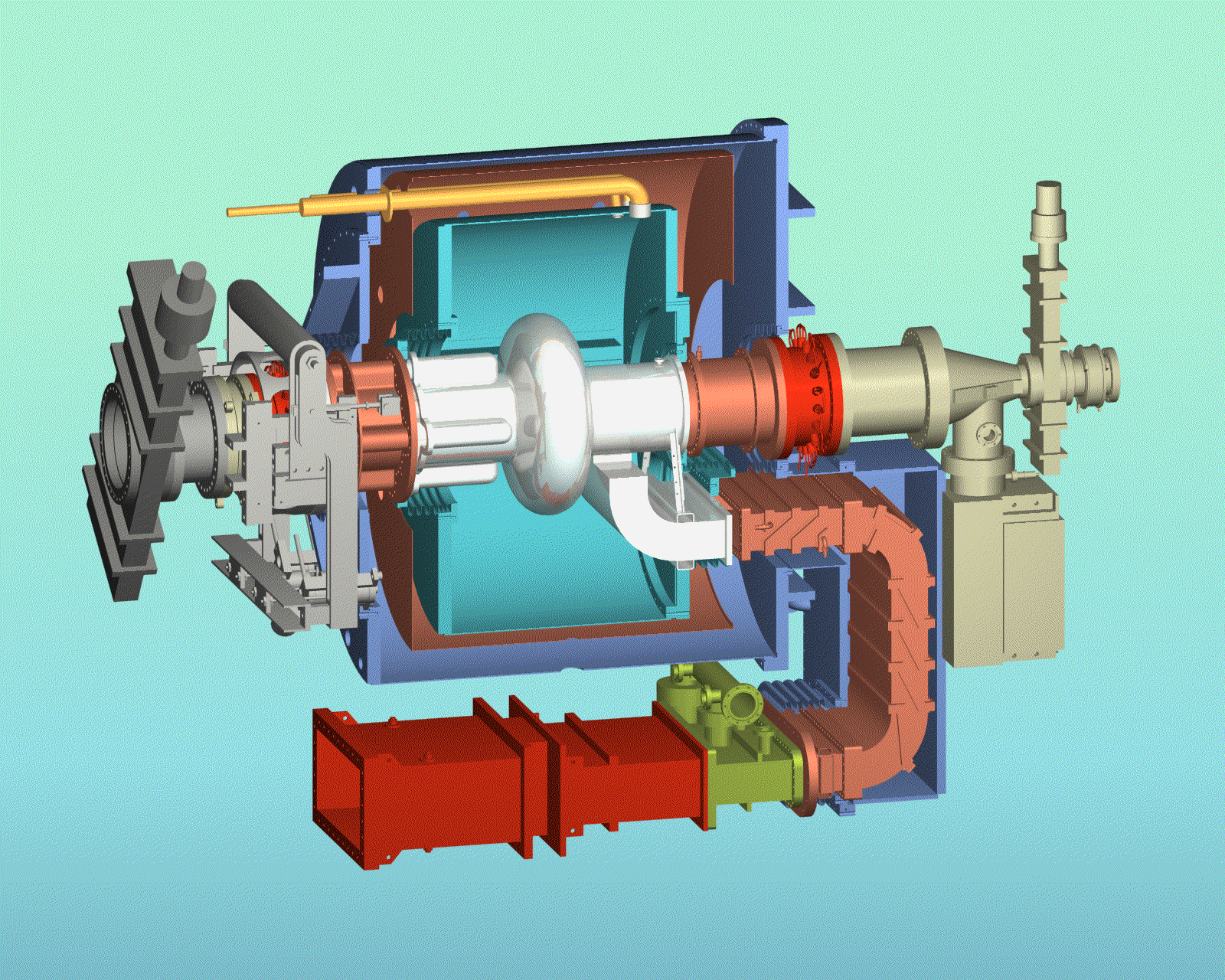
A 3D drawing below illustrates the Cornell MARK II SRF cryomodule. The 500 MHz single-cell superconducting niobium cavity resides inside a liquid helium (LHe) vessel, external to which is vacuum insulation, a thermal radiation shield maintained at liquid nitrogen (LN2) temperature, layers of magnetic field shielding material and superinsulation, followed by the room temperature vacuum vessel enclosure. The He vessel is gravitationally suspended inside the vacuum vessel by four Invar rods. Within vacuum envelope of the cryostat are thermal transition pieces on the round beam tube (RBT) and the "fluted" beam tube (FBT), and the rectangular waveguide, designed to keep radiation and conduction heat loads to the LHe bath at low level. Outboard of each beam pipe thermal transision is a room temperature beam line higher-order mode (HOM) load. Following the RBT HOM load is a taper and small gate valve leading to the CESR beam pipe. The FBT HOM load has an integral fixture ring around which the cavity tuner clamps. The tuner mechanically adjustst cavity frequency via longitudinal elastic deformation allowed by bellows joints between the beam pipe and He/vacuum vessels, with a large beam line sliding joint outboard of the HOM load. Following the large sliding joint is a large inter-cavity gate valve which maintains large aperture (24 cm) to an adjacent cryomodule. /www/pub/Home/Research/SRF/MarkIICryomodule/Cryomodule3Ddrawing.GIF The rectangular waveguide thermal transition incorporates a gaseous helium cooled heat exchanger (HEX). The next section is a double-E elbow cooled by LN2. Following this is a short thermal transition fron LN2to room temperature, a waveguide vacuum pumping section, and a ceramic vacuum RF window.
Four cryomodules are installed in CESR for routine operation.
References
- S. Belomestnykh, et al.Commissioning of the Superconducting RF Cavities for the CESR Luminosity Upgrade. In Proceedings of the 1999 Particle Accelerator Conference.
- S. Belomestnykh. The High Luminosity Performance of CESR with the New Generation Superconducting Cavities. In Proceedings of the 1999 Particle Accelerator Conference.
- E. Cojnacki and J. Sears. Superconducting RF Cavities and Cryogenics for the CESR III Upgrade. In Proceedings of the 1999 Cryogenic Engineering and International Cryogenic Materials Conference.
- To watch a movie of the MARK II cryostat assembly , download Final_Movie.avi file (49 MB).


