Effects of Bolt and Dowel-Pin Holes in 8-Pole Model,
Improved Field Calculation and Fit for 7-Pole 1.9 T Field,
and
Progress on 7-Pole 8/8 Model
CESRc Working Group Meeting
8 November 2002
Postscript files are also available:
Outline
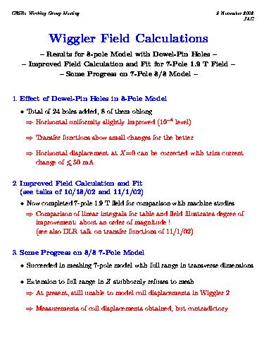
B_Y vs X_in in peak field region of center coil WITHOUT holes. This is the standard 8-pole model used until now.
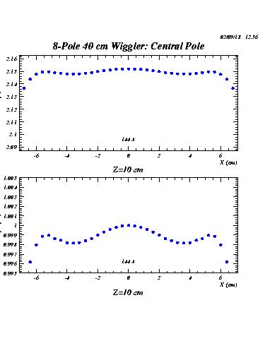
B_Y vs X_in in peak field region of center coil WITH holes. The missing field contribution from the iron now occupied by holes actually makes the field slightly more uniform. This model including the effects of the bolt- and dowel-pin-holes will now become the canonical model of the 8-pole wiggler.
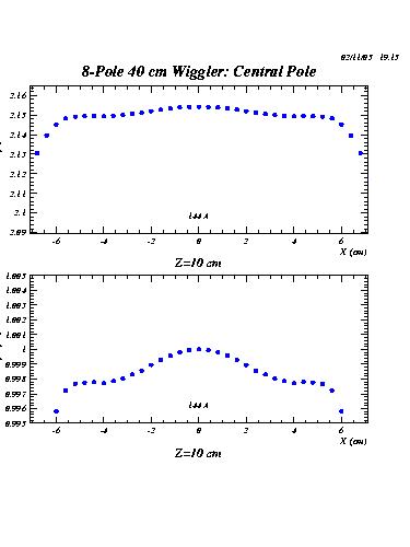
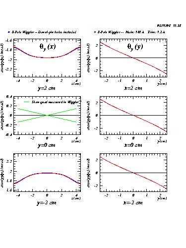
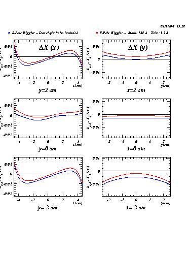
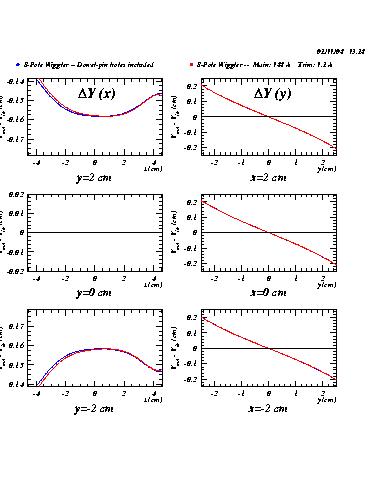
Transfer functions for 8-pole wiggler including holes.
These plots show comparisons for the transfer functions with and without holes. Differences are generally small. There is an offset in the displacement at X_in=0 of about 40 microns, which can be compensated by a change in trim current of
approximately 50 mA.
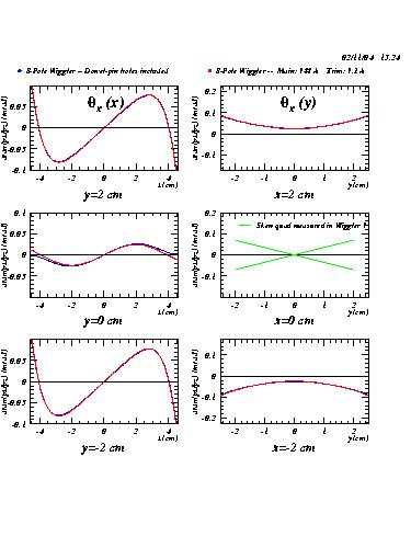
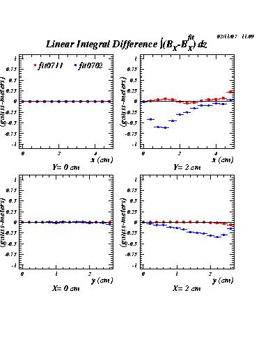
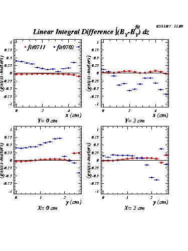
Linear integrals for old and new 7-pole 1.9T field tables/fits
One figure of merit used to judge the quality of the analytic fit function is how well the linear integrals over Z of the field components agree between
the table and the fit result. In these two plots, the differences between the linear integrals for the table and field are compared for the X and Y components of the field. They illustrate that the fit accuracy obtainable with the new method of field calculation is an order of magnitude better than was obtained with the old method.
Creation date: 11/08/02.